Fire Hose Pipes
Three professional-grade hose types for every application — from standard rubber-lined for commercial buildings to double-lined nitrile chemical-resistant hoses for oil refineries and petrochemical plants. Diameters from 38mm to 80mm. Exporting to 26+ countries.
Product Photos
in src=""
in src=""
in src=""
in src=""
Fire Hose Pipe Range
Three professionally manufactured hose types to match every installation environment — from standard commercial buildings to aggressive chemical processing environments in oil refineries and petrochemical plants.

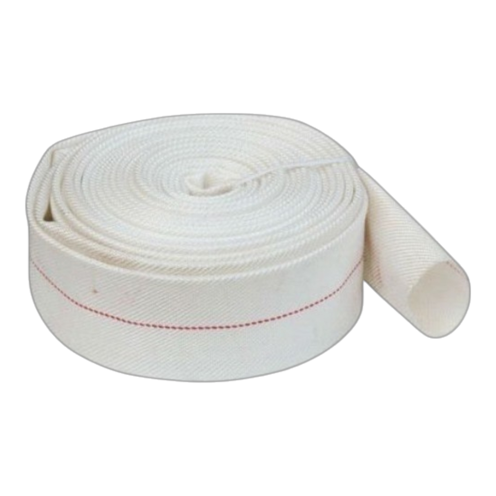
Type I — Standard
Single rubber-lined hose with a woven synthetic yarn jacket. The most widely specified hose for commercial buildings, hotels, shopping centres, and general indoor installations. Cost-effective and reliable.
- Working Pressure12 kg/cm²
- Burst Pressure36 Bar
- Diameters38 / 45 / 63 / 70 / 80mm
- Length / Roll10m / 15m / 20m / 30m
- Service Life10–15 Years
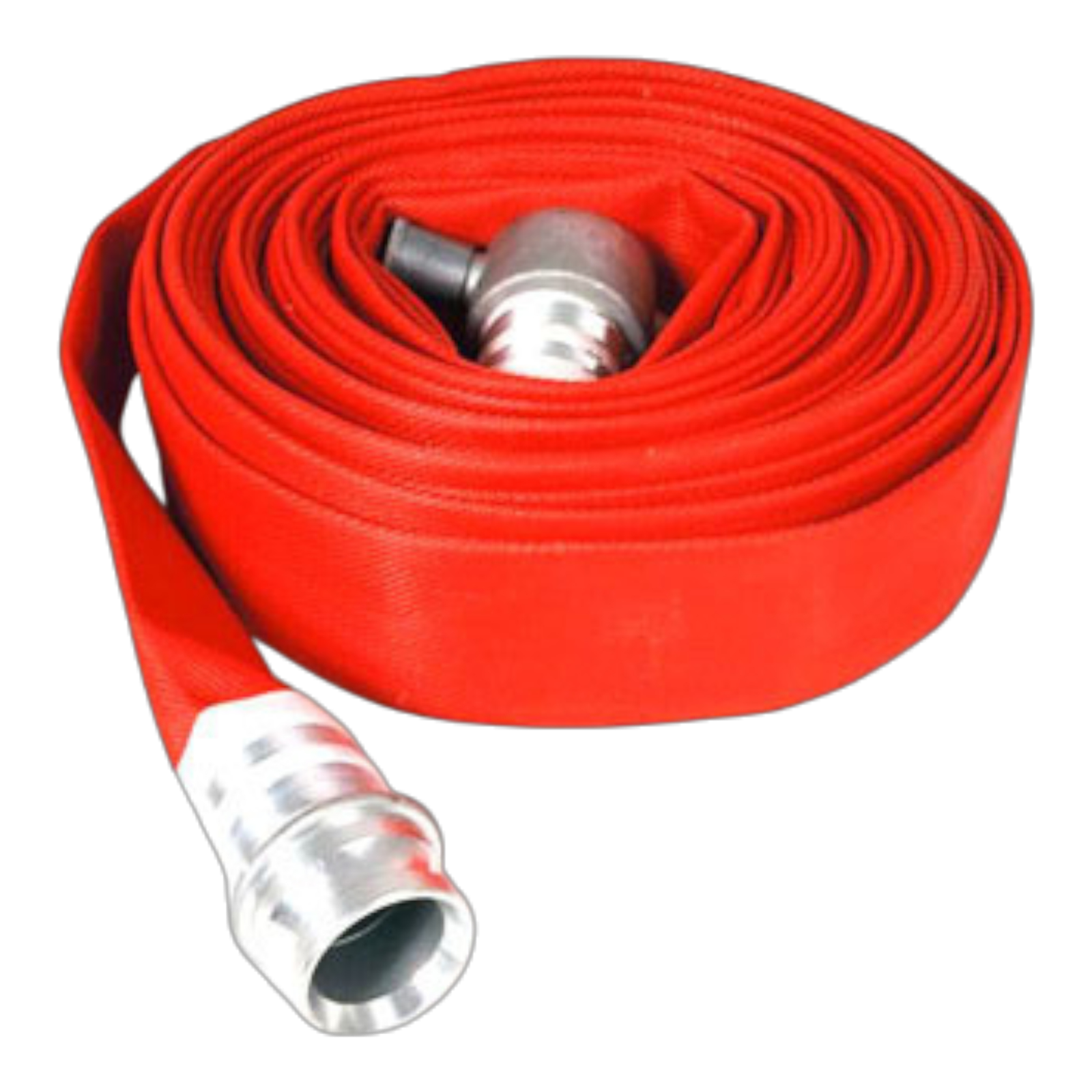
Type II — Industrial
Single rubber-lined hose with an external rubber coating over the woven jacket. The outer rubber layer provides exceptional abrasion, UV, and ozone resistance for demanding industrial and outdoor environments.
- Working Pressure18 kg/cm²
- Burst Pressure36 Bar
- Diameters38 / 45 / 63 / 70 / 80mm
- Length / Roll10m / 15m / 20m / 30m
- Service Life20+ Years
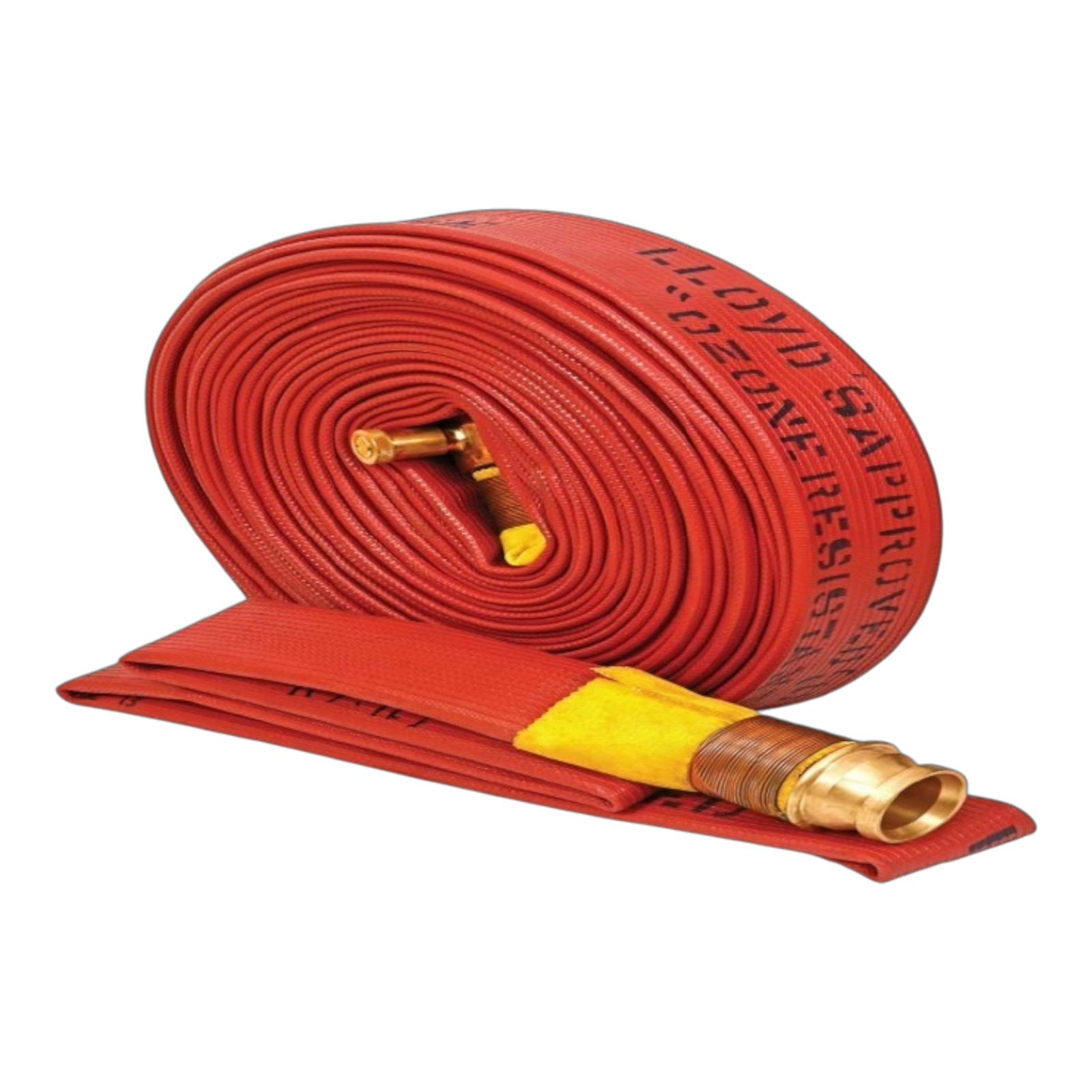
Type III — Chemical Grade
Double rubber-lined hose with a nitrile inner tube and external ribbed coating. Provides superior resistance to oil, fuel, foam concentrates, and chemical agents. The first choice for refineries, LNG terminals, and petrochemical plants.
- Working Pressure15–22 kg/cm²
- Burst Pressure36 Bar
- Diameters38 / 45 / 63 / 70mm
- Length / Roll10m / 15m / 20m / 30m
- Service Life25+ Years
Technical Specifications & Type Comparison
Side-by-side comparison of all three types — use this to select the correct hose for your working pressure, environment, and installation type.
| Parameter | 🔴 Type I | 🟠 Type II | ⚫ Type III |
|---|---|---|---|
| Construction | Single rubber lined | Single lined + external rubber coat | Double lined + nitrile inner |
| Working Pressure | 12 kg/cm² | 12 kg/cm² | 12 kg/cm² |
| Burst Pressure | 36 Bar | 36 Bar | 36 Bar |
| Diameters Available | 38 / 45 / 63 / 70 / 80mm | 38 / 45 / 63 / 70 / 80mm | 38 / 45 / 63 / 70mm |
| Roll Lengths | 10m · 15m · 20m · 30m (all types) | ||
| Jacket Material | Woven Synthetic Yarn | Woven Synthetic Yarn | High Tenacity Polyester |
| Inner Lining | Natural / SBR Rubber | Natural / SBR Rubber | Nitrile Rubber (Oil Resistant) |
| Outer Coating | ✗ No outer coat | ✓ Rubber outer coat | ✓ Ribbed rubber outer coat |
| Abrasion Resistance | Standard | High | Very High |
| Oil / Fuel Resistance | ✗ Not suitable | ✗ Limited | ✓ Excellent (Nitrile) |
| Foam Concentrate Service | ✗ Not recommended | ⚠️ Short term only | ✓ Fully compatible |
| UV Resistance | Standard (indoor) | Good (outdoor) | Excellent |
| Service Life | 10–15 Years | 20+ Years | 25+ Years |
| Primary Application | Commercial buildings / Indoor | Industrial / Outdoor | Refinery / Petrochemical / LNG |
| Relative Cost | Economy | Mid-range | Premium |
🔴 Type I — Diameter & Typical Flow
🟠 Type II — Diameter & Typical Flow
⚫ Type III — Diameter & Typical Flow
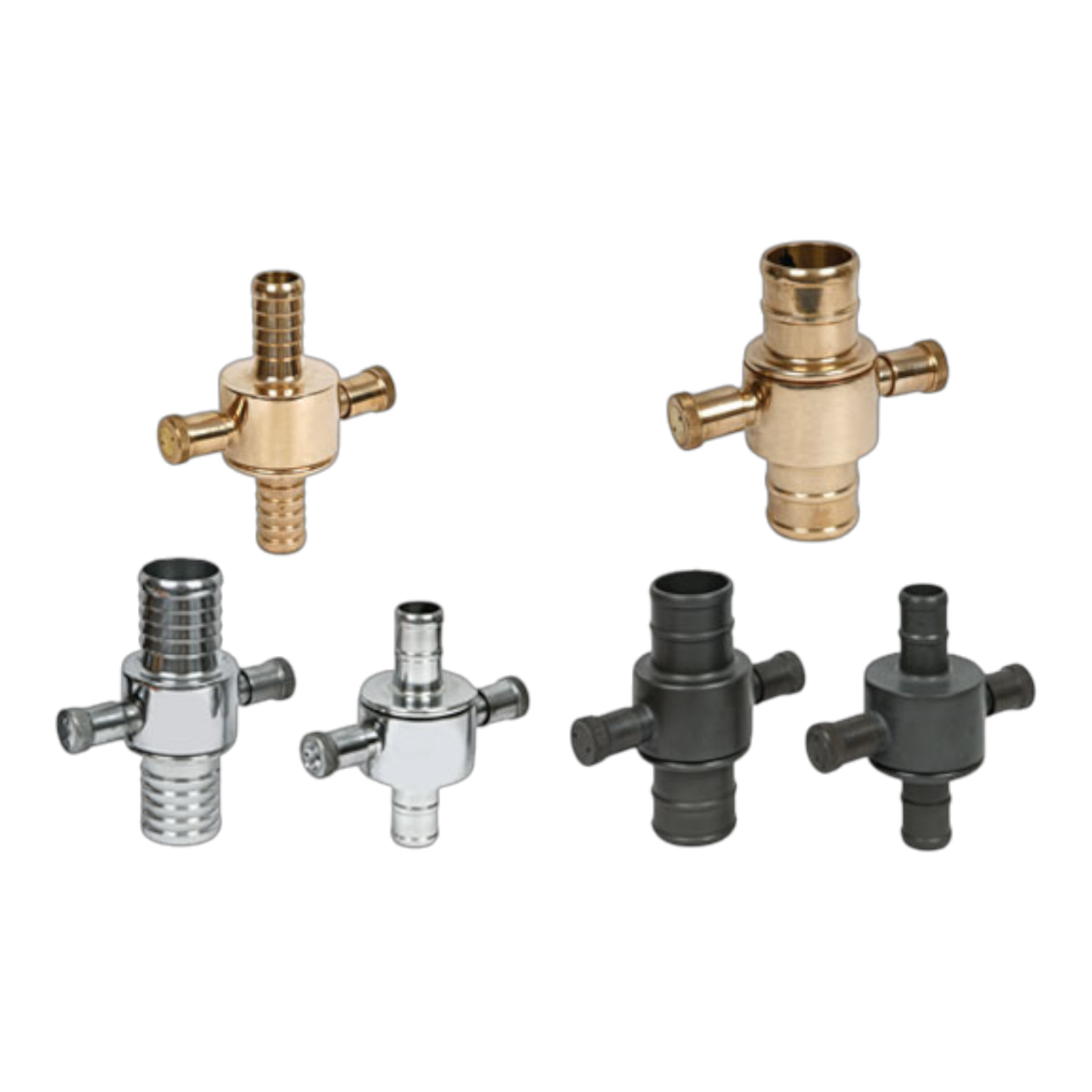
🔗 Coupling Options
All hose types available with Instantaneous (IS 903), Storz, BS Instantaneous, or plain end for on-site coupling. Specify coupling type and gender (male/female) at time of order. Custom lengths from 5m available on orders of 100m+.
🎨 Jacket Colours
Standard: Red (Type I), Orange (Type II), Black (Type III). Optional: Yellow, White, or custom colour on orders of 500m+. Colour coding helps identify hose type and pressure rating quickly during emergency deployment.
📋 Documents Supplied
Material Test Certificate (MTC), hydraulic pressure test certificate, packing list, country of origin certificate, and dimensional datasheet provided with every shipment as standard. No additional charges.
Where Are Fire Hose Pipes Used?
Kinde Fire hose pipes are installed across 10+ critical industry sectors globally — each requiring specific pressure ratings, lining materials, and environmental resistance.
Commercial Buildings
Hotels, shopping malls, office towers, and hospitals using Type I hoses in fire hose reel cabinets and fire hose stations — the most common application globally.
Type I — 38/45mmOil & Gas Refineries
Refinery firewater ring main hose stations and first-response teams using Type III nitrile hoses — the only correct choice for continuous oil and fuel exposure environments.
Type III — 45/63/70mmIndustrial & Manufacturing
Factories, steel plants, and large warehouses using Type II externally coated hoses for their superior abrasion resistance on rough concrete floors during industrial fire incidents.
Type II — 45/63/80mmLNG & LPG Terminals
Cryogenic terminal firewater systems with Type III nitrile hoses for compatibility with AFFF foam solutions used in LNG facility fire suppression systems.
Type III — 63/70mmAirports & Aviation
Aviation fuel farm hose stations, hangar fire systems, and ARFF support hose boxes — Type II for outdoor durability, Type III for fuel farm foam service lines.
Type II / Type IIIMarine & Shipboard
Vessel firewater systems, port terminal hose stations, and FPSO vessel deck hydrant hose boxes. Type III preferred for bilge and fuel exposure environments.
Type II / Type IIIMunicipal Fire Brigades
Urban fire department vehicle hose inventories and pump tender hose loads across India, Africa, and Middle East. Type I for structural response; Type II for general outdoor use.
Type I / Type IIPetrochemical Plants
Chemical process unit fire hose stations with continuous chemical splash and foam concentrate exposure — only Type III nitrile with ribbed outer coating is suitable.
Type III — All Diameters🏜️ Middle East & GCC
6 Countries🌍 Africa
6 Countries🌏 Asia Pacific
6 Countries🎯 Need Hose Pipes for a Specific Industry, Diameter, or Pressure Rating?
Share your application, hose diameter, working pressure, and quantity — we'll confirm the correct type and provide a price within 4 hours.
Troubleshooting & FAQ
18 real-world questions covering hose burst failures, coupling leaks, lining delamination, storage deterioration, correct type selection, sizing, and full maintenance schedules — tagged by type and deployment environment.
💥 Hose Burst & Pressure Failures
3 QuestionsRoot Cause: Over 70% of hose burst failures occur within 150mm of the coupling, not in the middle of the hose. The most common cause is incorrect ferrule crimping during the coupling assembly process — if the ferrule crimp diameter is outside tolerance (too tight cuts the jacket; too loose allows the hose to pull out under pressure), the burst point moves to just beyond the ferrule grip. The second most common cause is hose-end abrasion where the hose repeatedly bends sharply at the metal coupling edge during storage — this weakens the jacket wires at exactly that point and creates a stress concentration that fails under pressure test.
Fix: Inspect all coupling assemblies at the ferrule zone annually — look for any jacket fraying, cracking, or discolouration at the hose-to-coupling interface. Hose ends should be stored on a flat rack, not hanging from the coupling. When re-coupling a burst hose: cut back at least 200mm beyond the burst point to reach undamaged hose material, re-insert and re-crimp using the correct ferrule dimensions from the hose manufacturer's assembly datasheet. Never re-use a ferrule once crimped — replace with a new one. Always pressure test to working pressure (not burst pressure) as part of every new coupling assembly before returning the hose to service stock.
Root Cause: Mid-body failure is caused by mechanical damage to the jacket that was not identified before deployment. The jacket woven fibres carry the hoop stress that keeps the hose from bursting — when a section of jacket is abraded through (from being dragged over sharp concrete, metal edges, or through a doorway repeatedly), those fibres are severed and the remaining fibres carry progressively more load. The inner rubber lining alone cannot resist the burst pressure — once jacket coverage drops below approximately 60%, the burst point shifts to that damaged section. Kinking the hose at high pressure also concentrates stress and can cause an immediate mid-body failure.
Fix: After every deployment and during quarterly inspections, lay the hose out flat and run hands along the entire length feeling for soft spots, flat sections, or areas where the jacket feels thin or worn through. Any section where the inner lining is visible through the jacket, or where the jacket feels significantly thinner than the rest of the hose, must be flagged for replacement. Mark damaged sections with a permanent marker during inspection — do not return to service without repair or replacement. For environments with sharp edges (metal fabrication plants, timber mills), specify Type II for its rubber outer coat which provides an additional abrasion protection layer over the woven jacket.
Root Cause: Ballooning — where the hose expands locally to a visible bubble — means the jacket woven fibres at that point have separated, stretched, or been severed, and the rubber lining is now carrying the full burst load alone. The rubber is acting as a temporary balloon only — it has not yet ruptured but is under extreme stress. Ballooning is caused by: jacket damage from abrasion or chemical attack, UV degradation of synthetic fibres (particularly in outdoor storage), or localised overheating from fire radiant heat contact during deployment.
Immediate Action: A ballooned hose must be taken out of service immediately and condemned — it is not repairable. Do not re-pressurise it, do not attempt to reduce the balloon by squeezing it, and do not use it even at reduced pressures. Mark it clearly as condemned and remove from the hose stock. The burst point is structurally imminent at any pressurisation. Replace with a new hose length. If multiple hoses from the same batch are showing ballooning, inspect the entire batch and check storage conditions — widespread ballooning from a batch usually indicates UV or chemical degradation during outdoor storage without protective covers.
🔩 Coupling Leaks & Connection Problems
3 QuestionsRoot Cause: The instantaneous coupling (IS 903 pattern) relies on a flat rubber washer in the male coupling face to seal against the female coupling seat. Leaks at the face seal when locked indicate: (1) the rubber washer is hardened, compressed flat, or has a cut/nick on its sealing face; (2) the coupling face seat on the female half is corroded or has a physical nick that prevents full contact; or (3) the coupling is not being fully locked — the lugs must engage and the coupling must be rotated to the fully locked position with positive resistance felt. In hard water areas, lime scale buildup on the coupling seat face also prevents the washer from seating correctly.
Fix: Inspect the male coupling rubber washer first — it is the most common cause and the cheapest fix. Pull the washer out (it sits in a groove in the male coupling face) and check for hardening, compression set (less than 2mm thick), cuts, or deformation. Replace with a new EPDM washer of the correct diameter and thickness for the coupling size. Clean any scale from the female coupling seat using white vinegar on a soft cloth. If the female seat has a visible nick or corrosion pit deeper than 0.5mm, the coupling needs replacement — a nicked seat will continue to leak even with a new washer. Carry a full set of replacement washers in every hose maintenance kit — they are inexpensive and a common field failure.
Root Cause: A leak between the ferrule and the hose body means the hose is pulling out of the coupling under pressure — the ferrule crimp grip has failed. This happens when: (1) the original ferrule crimp was undersized (insufficient grip on the hose outer diameter); (2) the hose has been subject to repeated high-pressure surges that progressively work the hose tail out of the ferrule; or (3) the hose outer rubber has hardened and reduced in diameter with age, reducing the ferrule grip surface. In foam service hoses (Type III), foam concentrate chemical attack on the outer rubber shrinks and hardens it over time, causing exactly this failure mode.
Fix: This hose must be immediately taken out of service — a ferrule pull-out under live pressure will cause a sudden, violent failure that can injure operators. The hose cannot be repaired by re-crimping the existing ferrule. Cut back 200mm beyond the ferrule, fit a new ferrule on fresh hose material, insert the new tail into the coupling shank, and crimp to the correct diameter per the assembly specification. Always pressure test to 1.5× working pressure after re-coupling before returning to service. If multiple hoses from the same installation are showing ferrule leaks, the entire batch should be inspected and all couplings re-tested.
Root Cause: Aluminium instantaneous couplings corrode via two mechanisms in coastal and Gulf deployments: (1) galvanic corrosion when aluminium couplings are stored in contact with brass or stainless steel fittings — the aluminium acts as the anode and corrodes preferentially; (2) crevice corrosion in the lug engagement area where salt water or foam solution is trapped and concentrated during drying. White powdery aluminium oxide buildup in the lug slots makes the coupling very stiff and eventually prevents engagement entirely. In high-temperature Gulf storage (70°C+), the corrosion rate is 3–4× higher than in temperate climates.
Fix: Mild corrosion (white powder only, no pitting): clean with a soft brass brush and diluted citric acid (10% solution), rinse thoroughly with fresh water, dry completely, and apply a thin coat of silicone grease to the lug faces and engagement slots. Do not use steel wire brushes — they embed iron particles into the aluminium surface and accelerate further corrosion. Severe corrosion with pitting on the lug faces or seat: replace the coupling — pitted lugs will not make a reliable seal under pressure. Going forward, store hoses with the couplings face-to-face (engaged) to prevent moisture ingress into the lug slots, and use anodised aluminium couplings for coastal environments. Gunmetal (bronze) couplings are the correct specification for marine and highly corrosive environments.
🧱 Rubber Lining & Jacket Problems
3 QuestionsRoot Cause: Inner lining collapse or delamination from the jacket is caused by the adhesive bond between the rubber lining and the jacket failing. This bond is attacked by: prolonged exposure to foam concentrates (especially AR-AFFF in Type I rubber-lined hose — nitrile Type III is required for foam service), petroleum products being carried in the wrong hose type, or thermal degradation from repeated contact with hot surfaces during firefighting. Once the lining separates from the jacket, it collapses inward when the hose is unpressurised and partially blocks the bore, causing the flow reduction symptom described.
Fix: This hose is condemned — there is no repair for a delaminated lining. Once delamination begins, the loose lining material will continue to peel and can completely block the hose bore or break off in sections that block downstream nozzles during an actual emergency. Mark and remove from service immediately. Investigate the root cause before replacing: if foam concentrate is being used with Type I hoses, switch to Type III nitrile-lined hose for all foam service lines. This is the most common cause of premature lining failure in foam systems — using the wrong hose type for foam service.
Root Cause: The external rubber coating on Type II hoses is SBR (Styrene-Butadiene Rubber) in standard grade, which has a service life of 5–7 years under moderate outdoor conditions. However, in Gulf and tropical climates with continuous UV exposure and temperatures above 50°C on the hose surface (hoses stored on open racks in direct sun), SBR degrades in 3–4 years. Ozone cracking — the characteristic fine surface crazing pattern — is caused by atmospheric ozone attacking the rubber double bonds and is accelerated in industrial environments near transformers and electrical equipment. Small surface cracks are cosmetic initially, but once cracks reach the underlying jacket, moisture enters and accelerates jacket fibre degradation.
Fix: Surface crazing without through-cracks to the jacket: the hose is still serviceable but should be pressure tested and inspected internally. Apply a silicone-based rubber conditioner to the outer surface to slow further cracking. Monitor at every quarterly inspection. If any crack reaches or exposes the inner jacket weave, condemn the hose — moisture ingress to the jacket accelerates rotting of synthetic fibres from within. For Gulf deployments, specify EPDM or Neoprene outer coated Type II hose — both have significantly better UV and ozone resistance than SBR. Store all hoses in covered racks or UV-protective hose bags to substantially extend outer coat life.
Root Cause: Black rubber particles shedding from the inner lining into the water stream indicates the lining is in advanced deterioration. This is caused by: (1) the hose being stored for very long periods without use, causing the rubber to harden and develop microfractures that shed when water flows through; (2) biological attack — mould and bacteria growing on the inner lining surface during long-term wet storage; or (3) chemical incompatibility, where a substance carried in the hose has attacked the lining material and caused surface breakdown. This is a hygiene and operational safety issue — the rubber particles can block nozzles, damage pump seals, and contaminate the water supply.
Fix: Remove from service immediately. Do not flush it through and continue use — flushing dislodges more particles and creates a downstream contamination problem. Condemn the hose. Inspect the inner lining bore visually using a torch — if you can see peeling, flaking, or rough texture across the lining surface, the entire hose is condemned. For prevention: hoses stored for more than 12 months without use should be pressure tested and visually inspected internally before returning to service. Type I natural rubber-lined hoses are particularly susceptible — roll the hose onto a drum and flush with clean water, then inspect the discharge. If black particles appear, condemn and replace.
📦 Storage, Aging & Long-Term Care
3 QuestionsAlways dry before storage: This is the single most important rule. Hoses stored wet or damp develop mould on the inner lining within weeks in tropical climates. After every use or test, hang the hose vertically (or over a drying rack at a 45° angle) and allow complete drying of the inner bore — this takes 4–6 hours for a 30m length. Do not roll a wet hose and store it flat. Do not leave water standing inside the hose.
Storage environment: Store in a cool, shaded location away from direct sunlight. Maximum recommended storage temperature is 35°C — temperatures above this accelerate rubber compound degradation. Keep away from electrical equipment, generators, and transformers (ozone sources). Store hoses horizontally on open timber racks or perforated metal racks — never hang hoses from a single point as this creates a permanent kink at the support point over time. If outdoor storage is unavoidable, use UV-protective hose bags or covers.
Reel rotation: Hoses stored rolled on a drum should be re-rolled annually in the opposite direction to prevent permanent set at the roll curvature. Flat-folded hoses stored in cabinets should be re-folded at different points annually to prevent permanent crease marks on the jacket. A hose stored in the same fold for 5+ years will develop weakened jacket fibres at the fold line — these become burst points under pressure.
Do not deploy without testing first. A hose that has been in storage for 8 years may still be serviceable, but you cannot determine this by visual inspection alone. The rubber inner lining may have hardened and cracked internally without any visible external sign. The jacket fibres may have degraded from UV or moisture ingress. Coupling washers will almost certainly have compressed to a non-sealing thickness. Ferrrule grip may have reduced as the hose outer rubber has hardened and shrunk slightly in diameter.
Required pre-service testing for aged stock: (1) Replace all coupling face washers before testing — do not test with 8-year-old washers. (2) Visually inspect the full outer jacket for cracking, ballooning, or flat spots. (3) Inspect the inner lining bore using a torch for lining separation, mould, or rubber shedding. (4) Hydrostatic pressure test to working pressure (held for 3 minutes minimum) — any seepage, ballooning, or weeping through the jacket is an immediate fail. (5) Flow test — connect to a water supply and flush at full flow for 60 seconds, then check the discharge for rubber particles. A hose that passes all five checks is serviceable. One that fails any single check is condemned. Type I hoses beyond 10 years should generally be replaced regardless of condition as rubber degradation becomes structural at that age.
Root Cause: Mould on the inner lining is caused by storing hoses while still wet — even partially wet. In tropical climates (Kerala, coastal Karnataka, Bangladesh, Singapore, Nigeria), humidity inside a closed hose cabinet reaches 90–95% and a hose folded while damp will develop visible mould within 2–4 weeks. The mould grows on the rubber lining surface and degrades it over time by producing organic acids that attack the rubber compound.
Cleaning: For light surface mould (no deeper than the visible surface): flush the inner bore with a solution of 1 part white vinegar in 10 parts clean water, then flush with plain clean water, and dry completely before re-storing. For heavy mould with pitting or surface degradation visible: condemn the hose — mould has likely penetrated into the lining material and the structural integrity is compromised.
Prevention: Install ventilation slotting on hose cabinet doors if they are fully enclosed (drill 10mm vent holes in a grid pattern) to prevent moisture trapping. After any test or use, ensure hoses are completely dry before re-storing — verify by blowing air through the bore. In very humid climates, use silica gel desiccant sachets inside the closed hose cabinet and replace them every 6 months. Train all facility staff on the no-wet-storage rule — it is the single most effective prevention measure.
🔍 Type Selection & Sizing Questions
3 QuestionsMandatory choice: Type III — Double Lined Nitrile. A refinery or petrochemical plant fire hose station must use Type III for the following specific reasons: (1) Refinery firewater systems routinely carry AFFF or AR-AFFF foam concentrate solution — natural rubber (Type I) and SBR rubber (standard Type II) swell and delaminate on contact with foam solution within 12–18 months of foam service. Nitrile rubber (Type III) is fully compatible with all commercial foam concentrates. (2) Hoses in a refinery environment are regularly contaminated with crude oil, diesel, or process chemicals during use — nitrile resists all hydrocarbon exposure; natural rubber swells. (3) The ribbed outer coat on Type III provides superior abrasion resistance on metal grating, pipe racks, and concrete surfaces common to refinery deployments.
Diameter selection: For refinery hose stations per most international oil company standards — 45mm for standard hose reels in process units; 63mm for high-risk areas (tank farms, pump stations, loading arms); 70mm for monitor hose supply. Length: 20m or 30m depending on station spacing. Coupling: aluminium instantaneous for most process unit hoses; brass/gunmetal for marine or highly corrosive areas. Confirm specific project requirements against client specifications (Total, Shell, Aramco, ONGC all have company-specific fire hose standards that may exceed the minimum requirements).
For a 15-storey commercial building fire hose reel system (per NBC 2016 / IS 3844 India standards): Hose reel cabinets use 25mm (1″) non-collapsible semi-rigid hose — not lay-flat fire hose pipe. This is a distinct product from IS 636 lay-flat hoses. If you are asking about landing valve (wet riser) hose for the hydrant outlets on each floor, the correct size is 63mm (2.5″) lay-flat hose, 15m length, with instantaneous couplings, connected to the landing valve outlet. Type I is the standard specification for this application — the building interior environment does not require Type II or III.
Detailed sizing for the hydrant outlet hose: 63mm at 3.5 Bar residual pressure at the landing valve delivers approximately 450–500 LPM which is the fire brigade handline flow requirement. Each floor landing valve hose box should contain: one 15m Type I 63mm hose with coupling, one branch pipe (smooth bore 19mm tip), and one hose wrench. The building fire fighting water system pump must be sized to maintain 3.5 Bar at the most unfavourable landing valve (top floor) while simultaneously supplying the two highest hydraulic demand outlets. Confirm with the project fire consultant for final specification.
Not recommended for unshielded outdoor GCC storage. Type I natural rubber-lined hose is rated for 12 kg/cm² and has adequate pressure performance in Gulf climates, but the issue is storage degradation, not pressure capability. The inner natural rubber lining degrades when stored in environments above 40°C continuously — which is the norm for any outdoor storage in the GCC from May to October. Hose surface temperatures in direct sun in Saudi Arabia or UAE can reach 80–90°C, which is far beyond the safe storage temperature for natural rubber. After 2–3 summers of this exposure, the lining hardens, cracks internally, and the hose begins to lose burst pressure margin.
Correct specification for outdoor GCC: Use Type II for all outdoor hose stations — the external rubber coat is typically SBR or EPDM grade and provides UV and ozone protection to the jacket. For absolute longevity in GCC outdoor environments, request EPDM outer coat Type II which handles temperatures to 120°C. Additionally, install shade covers or louvred enclosures over all outdoor hose stations to reduce direct sun exposure — this alone can reduce hose surface temperature by 25–30°C and nearly double the effective service life of the rubber components.
🔧 Maintenance Schedule & Inspection
3 QuestionsAfter every use: Lay the hose out flat and flush the inner bore with clean fresh water immediately — removes foam concentrate, soot, and contamination that accelerates lining degradation if left in contact. Inspect the full length visually for damage during the flush. Dry completely before re-storing. Check coupling washers and replace if compressed or cut. Update the hose use log with date, incident type, and duration.
Monthly visual inspection: Unroll and inspect the outer jacket along the full length for cuts, abrasion, ballooning, or jacket cracking. Inspect coupling lugs for corrosion or physical damage. Check coupling face seating surfaces for scale or nicks. Confirm couplings connect and disconnect freely. Inspect hose storage condition — no wet or damp hoses in stock.
Quarterly (Gulf / Coastal / High-humidity deployments): Full unroll and inspection. Replace all coupling face washers regardless of apparent condition — rubber washers in hot climates lose sealing properties faster than temperate climates. Test coupling engagement with mating couplings. Re-roll hoses in opposite direction to prevent permanent set.
Annual hydrostatic pressure test: Connect each hose to a water supply through a pressure gauge and pressurize to working pressure. Hold for 3 minutes minimum. Inspect the full length for seepage through the jacket, coupling leaks, or ballooning. Record pass/fail in the fire equipment register with date and test pressure. Any hose failing the annual test is condemned and replaced. Update inspection tag on each hose. Hoses older than 10 years (Type I) or 20 years (Type II) should be replaced preventively regardless of test result.
Immediate action (within 2 hours of foam use): Do not allow foam solution to dry inside the hose — dried foam concentrate residue is extremely difficult to remove and forms a sticky layer that degrades the lining over time. Flush the inner bore immediately with a high-volume flow of clean fresh water for a minimum of 5 minutes per 30m hose length. The discharge should run completely clear with no foam bubbles before flushing is considered complete.
Full decontamination procedure: After the initial flush, submerge or soak the hose for 30 minutes in a container of clean water to dissolve any residual foam concentrate in the lining pores. Then flush again with clean water for a further 3 minutes. For hoses used with AR-AFFF (alcohol-resistant foam), add a 5% white vinegar solution flush after the water flush — this neutralises the polysaccharide component of AR-AFFF which is particularly adhesive to rubber. Final rinse with plain clean water. Hang to dry completely before re-storing.
Important: Even Type III nitrile-lined hoses have a finite resistance to AFFF — prolonged soaking without decontamination does cause slow degradation. No hose type should have foam solution sitting in it for more than 6 hours without flushing. Keep a foam decontamination log to track how many foam exposures each hose has experienced — hoses with more than 20 foam deployments should be inspected internally and linings checked for early delamination signs regardless of age.
Step 1 — Determine the protection radius per station: Each fire hose station protects a circular area equal to the total hose length run plus 6m (nozzle throw distance). For a 2 × 15m hose lengths coupled together = 30m run + 6m throw = 36m protection radius. For a 30m single length = 30m + 6m = 36m. Hose stations should be positioned so every point in the facility is within the protection radius of at least one hose station. In process areas with obstructions (pipe racks, vessels), use 0.7× the geometric radius as the effective coverage radius to account for routing around obstacles.
Step 2 — Calculate number of stations: Divide the total facility floor area by the effective coverage area per station. For a 36m radius: effective area = π × (36 × 0.7)² = π × 25.2² = approximately 2000m² per station for an obstructed industrial layout. For a 10,000m² facility: 10,000 ÷ 2000 = 5 stations minimum. Add 20% for overlap and coverage of extremities — round up to 6 stations.
Step 3 — Hose quantity per station: Standard industrial hose station: 2 × 15m or 1 × 30m lengths per station for 63mm diameter. High-risk areas (pump stations, tank manifolds): 2 × 20m lengths. Confirm hose station layout with the project fire protection engineer and cross-reference against local authority requirements — some GCC municipalities specify minimum hose lengths and station spacing that may exceed the calculated minimum. Contact Kinde Fire with your facility area, process type, and local fire code for a complete station layout recommendation.
🎯 Need Help Selecting the Right Hose Type or Diameter?
Our technical team responds within 4 hours — share your application and we'll confirm the correct hose type, diameter, and quantity.
Ready to Source Professional
Fire Hose Pipes?
Share your hose type, diameter, length, coupling standard, and quantity — we'll confirm the correct specification and provide pricing within 4 hours. Type I, II & III in stock. Exporting to 26+ countries with full documentation.
🔴 Type I — Standard
- Single rubber lining, synthetic yarn jacket
- Working pressure: 12 kg/cm²
- Diameters: 38 / 45 / 63 / 70 / 80mm
- Service life: 10–15 years
- Best for: Hotels, offices, malls, indoor
- Relative cost: Economy
🟠 Type II — Industrial
- Single lined + external rubber outer coat
- Working pressure: 18 kg/cm²
- Diameters: 38 / 45 / 63 / 70 / 80mm
- Service life: 20+ years
- Best for: Factories, warehouses, outdoor
- Relative cost: Mid-range
⚫ Type III — Chemical Grade
- Double lined, nitrile inner + ribbed outer
- Working pressure: 15–22 kg/cm²
- Diameters: 38 / 45 / 63 / 70mm
- Service life: 25+ years
- Best for: Refineries, LNG, petrochemical
- Relative cost: Premium
🔩 Coupling Standards Available
- IS 903 Instantaneous (Male / Female)
- Storz — 52mm / 65mm
- BS Instantaneous
- Plain end for on-site coupling
- Custom lengths from 5m (min 100m order)
- Aluminium / Gunmetal / Brass coupling
🎨 Jacket Colours & Finishes
- Type I standard: Red jacket
- Type II standard: Orange / Red jacket
- Type III standard: Black jacket
- Custom colour on 500m+ orders
- EPDM outer coat: Gulf / Tropical spec
- White jacket available for clean-room use
📋 Documents Supplied
- Material Test Certificate (MTC)
- Hydraulic Pressure Test Report
- Dimensional Drawing / Datasheet
- Packing List & Country of Origin
- Coupling Assembly Specification
- Maintenance & Inspection Guide